


4 Tips to identify genuine Lifud drivers
Wiring of Triac Dimming & Wireless Dimming
4 Steps to Enable 0/1-10V Dimming Wiring
4 Steps to Enable DALI Dimming Wiring
What is DALI Intelligent System?
Two Kinds of Dimming Curves for DALI Projects You Should Know
What's the Future of Intelligent LED Lighting?
Wiring of Triac Dimming & Wireless Dimming
In the previous posts, we have learned about the wiring of DALI and 0-10V dimming in 4 steps. Today, it’s time for Triac and wireless dimming.
Firstly, we will introduce triac dimming wiring.
Before wiring, it’s necessary to know about various parts in the whole circuit and interfaces of devices. Unlike 0-10V and DALI dimming, triac dimming doesn’t need additional signal wires. It functions by controlling the input live wire. So its wiring will be easy relatively.
1. Wiring of Triac Dimmer:
①One wiring is as shown in the following picture, all INPUT and OUTPUT interfaces function as the AC IN / AC OUT interfaces of 0-10V dimmer. The electricity L/N is input from INPUT and output from OUTPUT to strong electric interface of the LED driver.
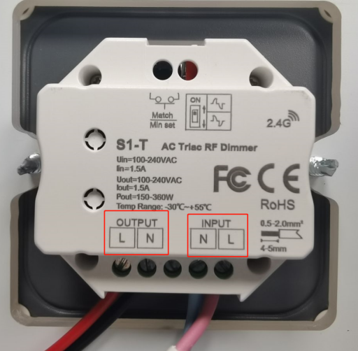
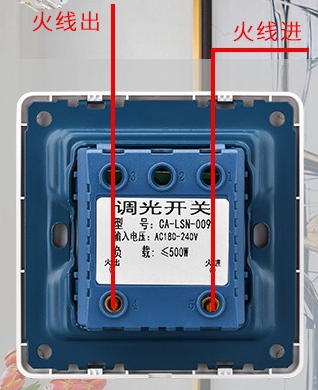
②The other one is single live wire connecting. The input interface only connect to the live wire of electricity and the output interface connects to the L interface of the LED driver.
③As shown in the picture, some dimmers are equipped with a DIP switch. The dimmer can be adjusted to be leading edge or trailing edge dimming according to the LED driver.
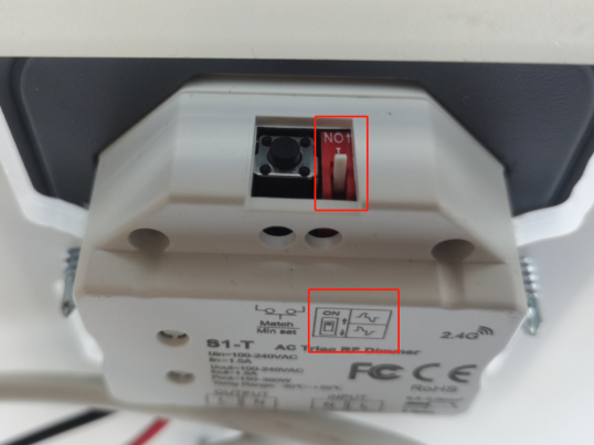
*Some triac dimming LED drivers only supports leading edge (or trailing edge) dimming, so please check whether the dimmer is compatible with the LED driver before powering it on.
*Lifud triac dimming LED driver supports both leading edge and trialing edge dimming.
2. Interface of LED driver: L/N (strong electric input); LED+/LED- (output interface, connect to the light)
Now we can go for wiring.
Step 1: Connect L/N of the LED drivers to OUTPUT of the dimmer.
Step 2: Connect LED+/LED- of the LED driver to the input interface of the light.
Step 3: Connect INPUT of the dimmer to electricity.
*Remark: Before powering on, check the DIP switch on the dimmer to make sure that the dimming mode (leading edge or trailing edge dimming) is compatible with the LED driver.
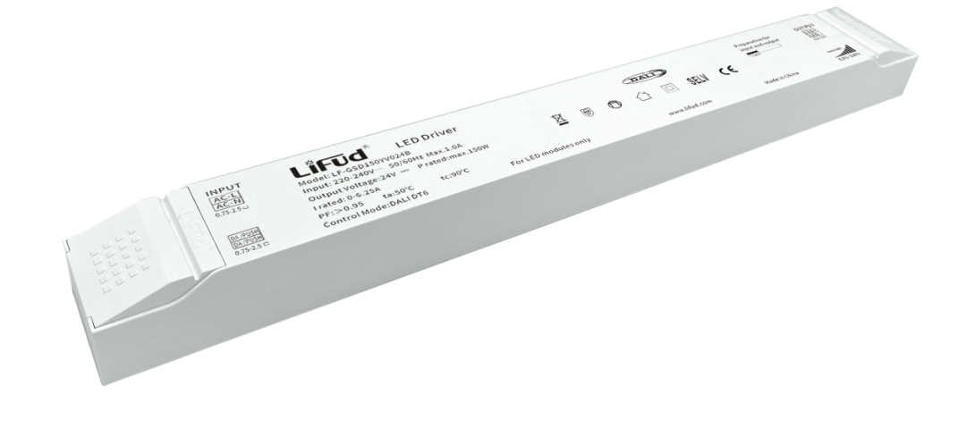
The LED driver shown in the video is Lifud’ s constant voltage triac dimming series---LF-GATxxx. Its dimming depth can reach 0.1%. If interested, please contact us at sales@lifud.com.
Product Details
Power: 75/150W
Output Voltage: 24V
Dimming: leading edge and trailing edge dimming, smooth & flicker free in the whole dimming process
Dimming Depth: 0.1%
Certifications: CE, CB, ENEC, RCM, CCC
Warranty: 5yrs
Application: LED strip
Now Let’s introduce wireless dimming LED driver briefly.
In terms of wiring, wireless dimming product is easier than any other intelligence dimming products. Its wiring is the same as non-dimmable LED driver. Firstly, connect the LED driver to the light. Secondly, connect all LED drivers, dimmer, gateway and any other devices to electricity. Then it functions via the software and gateway.
For the gateway, it requires an adaptor to connect to the electricity. Today we mainly talk about dimming wiring. In the future, we will share more about wireless control.
The above is all for today’s sharing. Follow Lifud for more about LED driver.
Previous article
Previous article

Lifud Technology Co., Ltd.
Tel: +86-0755-83739299
Email: sales@lifud.com
Add: 3A, Block B, Building 1, Xingzhan Plaza, No.446, Nanhuan Rd., Shajing St., Bao'an Dist., Shenzhen, Guangdong, China


SAF Coolest v1.3.1.2 设置面板 AXUSX-ZAVJ-FFXZE-ESV
No results for now
Sorry,No results for now
You can view other sections or go back HOME