


4 Tips to identify genuine Lifud drivers
Wiring of Triac Dimming & Wireless Dimming
4 Steps to Enable 0/1-10V Dimming Wiring
4 Steps to Enable DALI Dimming Wiring
What is DALI Intelligent System?
Two Kinds of Dimming Curves for DALI Projects You Should Know
What's the Future of Intelligent LED Lighting?
4 Steps to Enable 0/1-10V Dimming Wiring
In the previous posts, we have learned about the DALI dimming and its system wiring. Today, 0/1-10V dimming wiring will be introduced.
Dos and Don ’ts for 0/1-10V Dimming Wiring
Before wiring, we should learn about the following notes.
1. Independent dimming signal wire is necessary for 0/1-10V dimming, and the signal wire must designate positive and negative.
2. The total signal current consumed by the LED driver signal interface must be less than the current on the dimming signal wire:
2mA*quantity of LED driver ≤ the current on the dimming signal wire
Remarks:
①According to IEC60929, the signal current consumed by every 0/1-10V LED driver signal interface should be ≤2mA.
②The signal current on the signal wire is from the 0/1-10V LED dimmer. Different dimmer has its own signal current. For details, please refer to the instructions of the dimmer.
For example:
A dimmer that outputs signal current of 50mA can carry up to 25pcs of LED drivers.
3. At 0/1-10V dimming mode, all lights on a signal wire are in one loop, which can only be controlled in a unified way (through knob, panel and other dimmers). If it needs to be controlled in different scenes, multiple loops need to be added through the module. In this situation, the scene can be programmed.
4. Generally, the 0-10V dimming signal can control the LED driver directly to achieve dim-off.
5. When 1-10V dimming signal is used with some drivers, it may not be able to dim to off. It is necessary to add a relay between AC and the LED driver to turn off the AC input to dim off the light. In this case, the 1-10V dimmer generally integrates with a relay, and the LED driver connects to electricity through the dimmer’s AC OUT (as shown in the picture below).
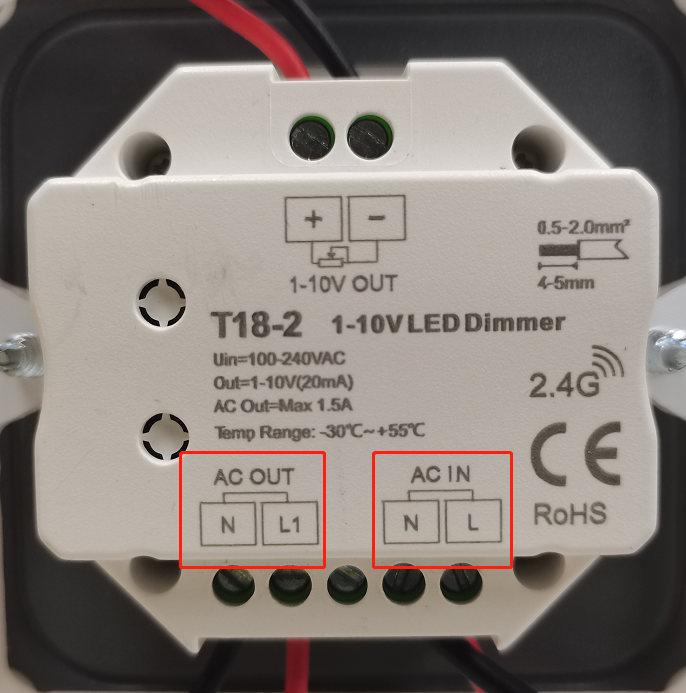
The electricity is input from AC IN and output from AC OUT to AC interface of LED driver, and output to signal wire interface of the driver through 1-10V OUT.
Wiring of Single Loop and Multi Loops
Wiring of single loop:
1. Connect DIM+/DIM- (interface of signal wire) of all LED drivers with 0/1-10V OUT (output terminal) of the dimmer.
*Pay attention not to overload the number of LED drives and not to connect the positive and negative electrodes reversely.
2. Connect AC-N/AC-L (access to electricity) of all LED drivers with AC OUT (N/L1) of the dimmer.
*If the dimmer doesn’t integrate with a relay, this step should be omitted. Connect AC-N/AC-L of all driver and AC IN of dimmer with electricity directly.
3. Connect the output electrodes (LED+/LED-) of driver with input electrode of the light.
4. Connect AC IN of the dimmer with electricity.
*After wiring, pay attention to check the circuit before powering it on, otherwise the 0/1-10V signal wire connected with strong electricity will cause the device breaking down.
Wiring of multi loops:
For multi loops wiring, the wiring steps of each loop are the same. It should be noted that there may be differences among different system modules. The following is just an example:
1. All LED drivers in the same loop: connect AC-L to the same AC OUT of the 0-10V module (L1 or L2 or L3 or L4); connect the signal wire interface DIM+/DIM- to L1 or L2 or L3 or L4, or the corresponding 0-10V signal output port.
*Pay attention not to connect the positive and negative electrodes reversely.
2. Connect 24V/GND to the power supply port of the scene panel; connect D+/D- to signal interface of the panel.
*Different brands of modules may have 12V and other situations. But the interface functions as providing power supply and signal for the panel. For details, please refer to the instructions of the module.
3. Connect the output electrodes (LED+/LED-) of driver with input electrode of the light.
4.All L/N interfaces of the modules and neutral wires of all LED drivers connect with electricity.
Dimming Effect of Lifud 0-10V Driver
We use Lifud 0-10V dimming LED driver LF-AAAxxx series to practice the wiring process and demonstrate the dimming effect. Please click https://mp.weixin.qq.com/s/nQbdYudXcwQ6xRlCjpSRHQ for the video.
FAQs
A1: If connect the positive and negative electrodes of the 0/1-10V signal wire reversely, will the LED driver be burned?
Q1: No. But the driver will be on or off for a long time, which is out of control. For Lifud 0-10V driver, if signal wire is connected reversely or has short circuit, the driver output is 0; if the signal wire is in the state of open circuit or not connected, the driver output reaches 100%.
A2: Why can’t the light go off completely when used with a 0-10V dimming LED driver? How to solve the problem?
Q2: When the minimum output signal of the dimmer is greater than the turn-on voltage signal of the driver, the dimmer can not turn off the light, and the light can only be turned off when the strong electric is cut off. This problem can be solved by replacing with a matched dimmer or a dimmer integrated with a relay. For example, Lifud 0-10V driver, the turn-on voltage is about 0.5V. When the dimming signal voltage is less than 0.5V, the light can be turned off. The minimum output signal of the dimmer and the turn-on signal of the LED driver can be inquired according to the specification.
A3: Is there a transmission distance limit for 0-10V signal? If so, how far is it?
Q3: Yes, the transmission distance of 0-10V signal wire is related to the wire’s material, wire’s diameter and the number of connected drives. In practical application, it is recommended to use copper wire of 1.5 square millimetre, and the distance should be controlled within 100 meters. The signal amplifier can be added according to the actual situation. And the strong electric wire and signal wire should be wired separately to prevent the interference of strong electric to the signal.
Previous article
Previous article

Lifud Technology Co., Ltd.
Tel: +86-0755-83739299
Email: sales@lifud.com
Add: 3A, Block B, Building 1, Xingzhan Plaza, No.446, Nanhuan Rd., Shajing St., Bao'an Dist., Shenzhen, Guangdong, China


SAF Coolest v1.3.1.2 设置面板 AXUSX-ZAVJ-FFXZE-ESV
No results for now
Sorry,No results for now
You can view other sections or go back HOME