


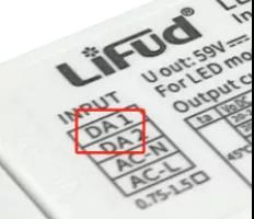
4 Tips to identify genuine Lifud drivers
Wiring of Triac Dimming & Wireless Dimming
4 Steps to Enable 0/1-10V Dimming Wiring
4 Steps to Enable DALI Dimming Wiring
What is DALI Intelligent System?
Two Kinds of Dimming Curves for DALI Projects You Should Know
What's the Future of Intelligent LED Lighting?
4 Steps to Enable DALI Dimming Wiring
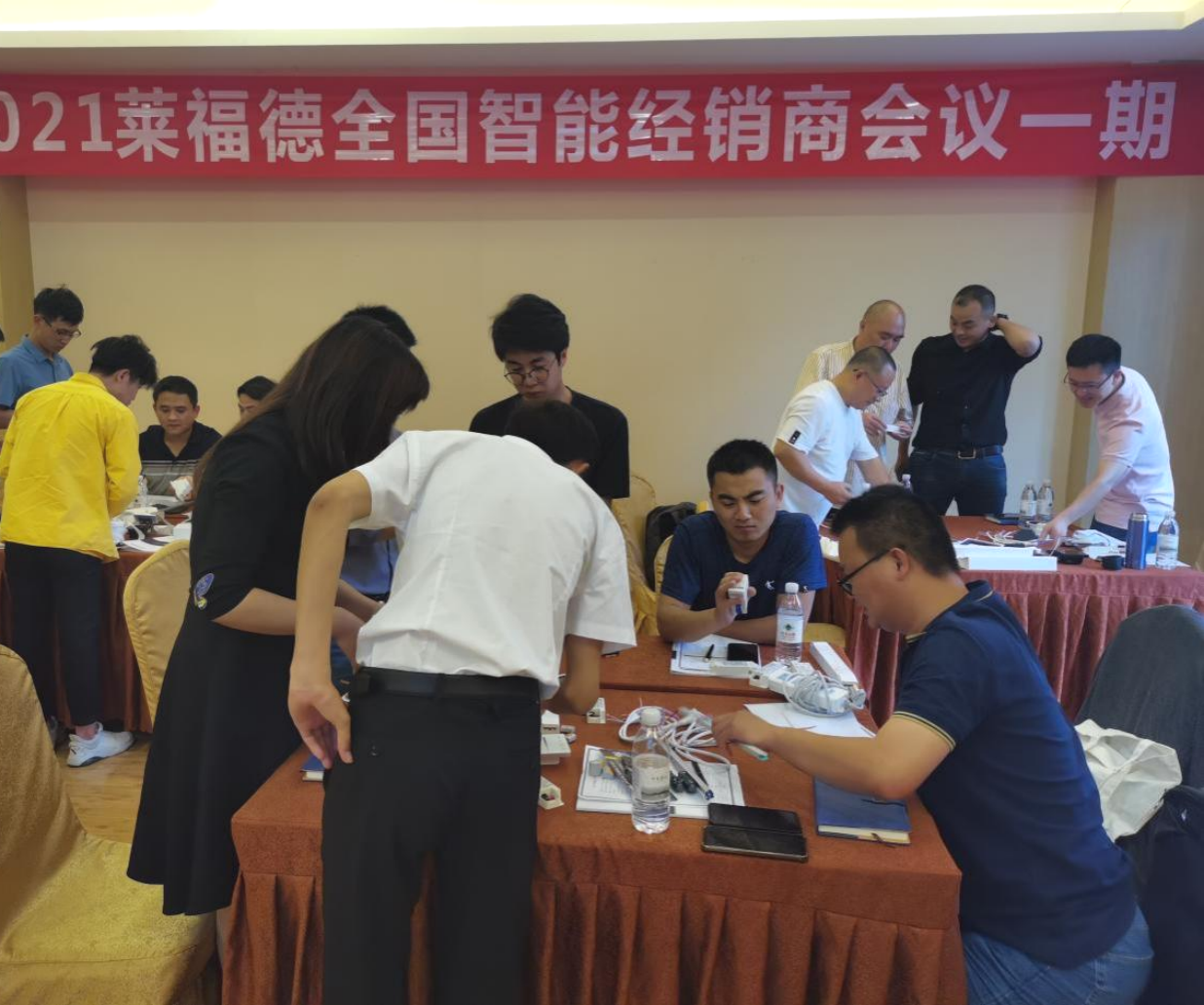
In late May, Lifud held the First Intelligent Product Distributor Conference, sharing dimming knowledge and conducting intelligent dimming wiring training. We hope to provide valuable technical service for every customer.

Actually, the wiring of intelligent dimming system (DALI, 0-10V, triac, Zigbee) is not complicated as we might think. Today, let’s have a look at the wiring of DALI dimming system.
Wiring of DALI System
Compared with ordinary lighting circuit, DALI dimming circuit has 2 additional signal wires. The signal wire does not designate positive or negative (the terminal with "DA" mark on all DALI components means the access port of DALI signal wire), so it is not difficult to finish wiring after understanding the power supply circuit required by each component.
- DALI signal wire and 24V auxiliary power supply wire, and part of the circuit of bus power supply output the voltage and current that DALI signal wire needs
- DALI control panel: connect with DALI signal wire and 24V auxiliary power supply wire
- DALI knob: connect with DALI signal wire
- DALI sensor: connect with DALI signal wire
- DALI LED driver: connect with DALI signal wire and electricity L/N
- Switch power supply: connect with electricity L/N, output voltage of 24V auxiliary power supply
Now we can connect the wires.
Wiring of Independent DALI System (connect with DALI master, programming available at anytime)
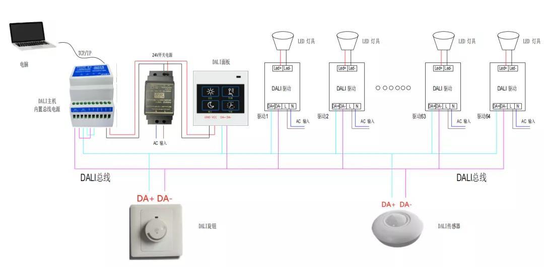
The above diagram is for reference:
①Connect DALI signal wires of all LED drivers, panel, knob and sensor to DALI signal power supply ports on the master in parallel (blue/purple line in the diagram is for DALI signal wiring circuit)
②Connect the master and panel to the 24V auxiliary power supply ports on switch power supply (red/black line in the diagram is 24V power supply circuit)
③Connect the output terminals of LED driver (LED+/LED-) to the input terminals of the light fixtures
④Connect the switch power supply and all LED driver to electricity (line with AC marked in the diagram)
Note:
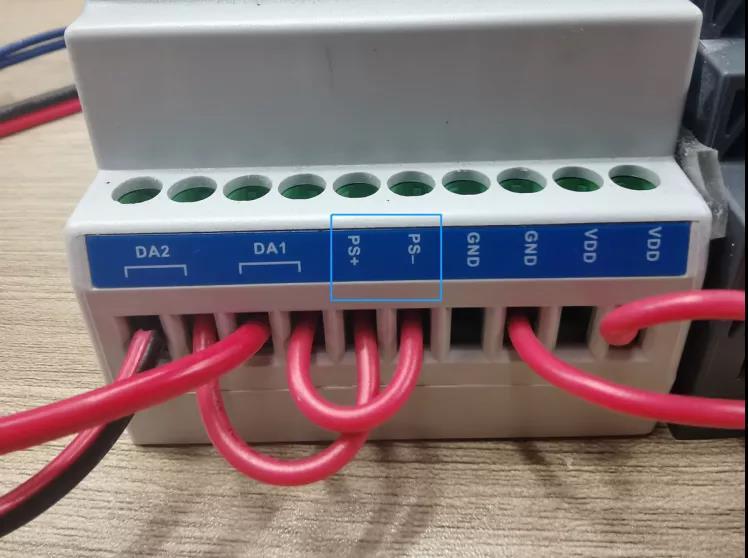
①As shown in the picture, the DALI master integrated with bus power supply has independent output terminals (PS+/PS-). Two wires connect PS+/PS- terminals with DA terminals, which connects bus power supply to the DALI bus actually. Sometimes, the DALI master integrated with bus power supply shares the same DALI terminal, or there should be an individual bus power supply if an integrated one is not equipped.
②Some masters can connect to electricity directly, not necessary to connect with 24V auxiliary power supply
③Some control panels can connect to DALI bus directly, not necessary to connect with 24V auxiliary power supply
Wiring of Panel/Knob (Not connect to the master, dim as the pre-set mode)
When there is no master, an individual bus power supply is needed for powering the DALI signal wire. Because the bus power supply is integrated with the master generally.
DALI bus power supply: connect to electricity, output the voltage and current that DALI signal wire needs.
①Connect DALI signal wires of all LED drivers, panel, knob and sensor to DA ports on the bus power supply in parallel
②Connect the control panel to the 24V auxiliary power supply ports
③Connect the output terminals of LED driver (LED+/LED-) to the input terminals of the light fixtures
④All LED drivers connect to electricity
After connecting the wires, let’s have a look at the dimming effect of Lifud DALI dimming LED drivers.
Dimming Effect
Today, we take Lifud new DALI DT6 LF-AADxxx series as an example.
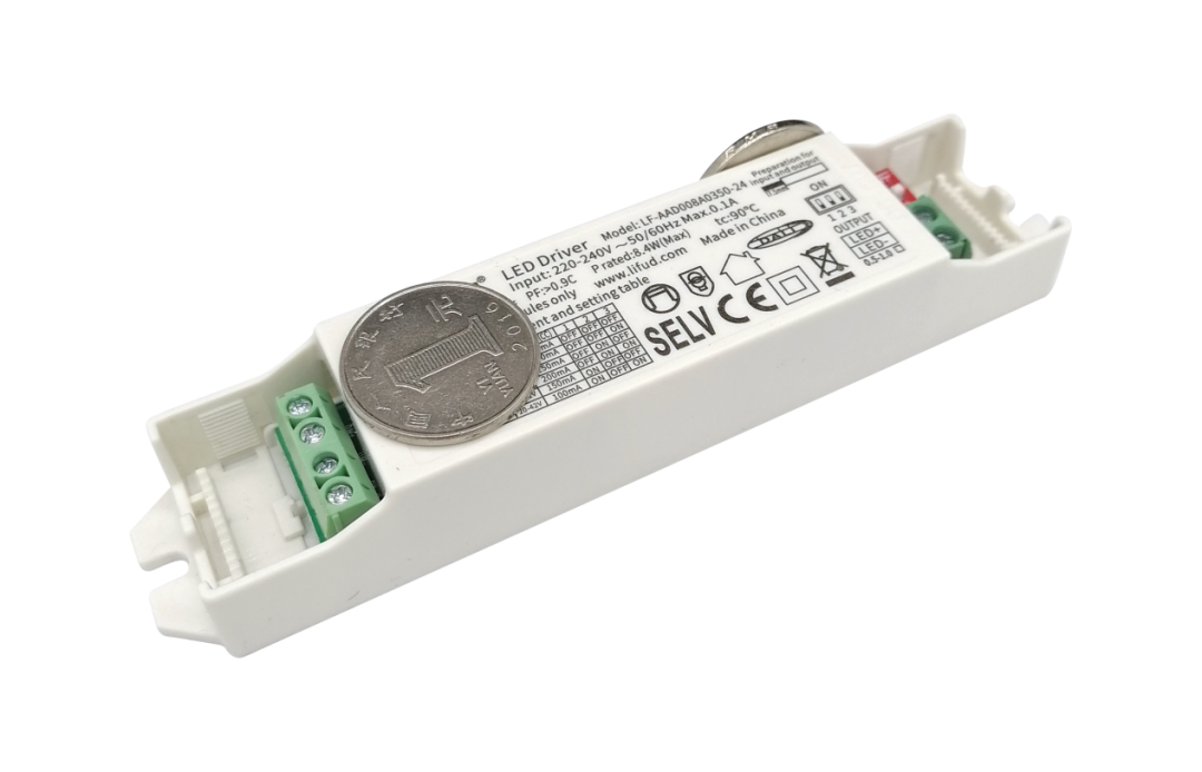
This product has filled a gap in China DALI dimming LED driver market. It has ultra small size, comprehensive certifications, 0.1% dimming depth and extraordinary flicker free effect. During the intelligent product release conference early this year, LF-AADxxx series attracted great attention.
Product Details
Power:8/12/20/40W
Dimming: DALI, Push (with memory function)
Dimming Depth:0.1%
Current: adjustable via the DIP switch from 100mA to 1050mA, 50mA a step
Dimming Curve: optional logarithmic curve or linear curve (compatible with various dimmers to achieve smooth dimming)
Size:141*30*21 (8W), 122*40*25 (12/20W), 141*40*25 (30/40W)
Certifications:DALI2.0, CE, CB, ENEC, RCM, CCC
Warranty: 5yrs
Applications: spot light, down light, panel light and etc
That’s all for today’s sharing. For more information about intelligent dimming and LED driver, please follow Lifud.
Previous article
Previous article

Lifud Technology Co., Ltd.
Tel: +86-0755-83739299
Email: sales@lifud.com
Add: 3A, Block B, Building 1, Xingzhan Plaza, No.446, Nanhuan Rd., Shajing St., Bao'an Dist., Shenzhen, Guangdong, China


SAF Coolest v1.3.1.2 设置面板 AXUSX-ZAVJ-FFXZE-ESV
No results for now
Sorry,No results for now
You can view other sections or go back HOME